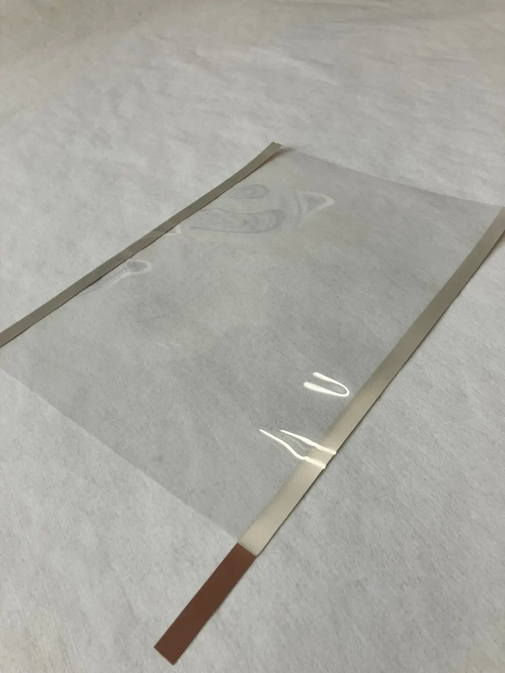
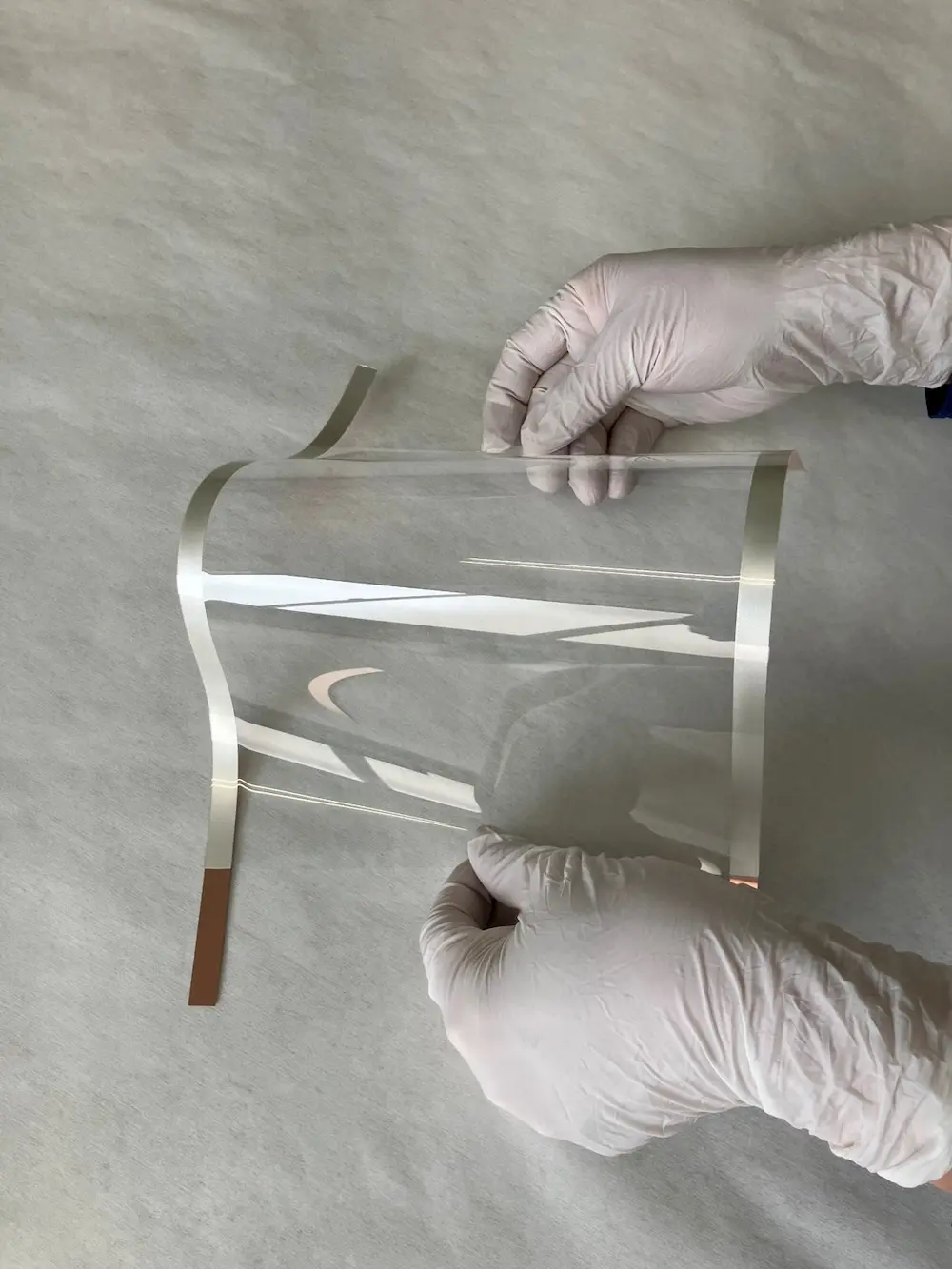
Perovskite solar cells offer major advantages by using a light-absorbing material known as a perovskite crystal, enabling high optical absorption coefficients, low-temperature processing, and lightweight, flexible designs at the same time. At the research stage, power conversion efficiencies have already reached the 26% range, approaching levels comparable to monocrystalline silicon. Because printing methods and roll-to-roll technologies can also be applied, perovskite solar cells are expected to enable low-cost production and deployment on large-area flexible substrates, which have been difficult to achieve with conventional solar cells.
Another important advantage is the wide range of potential applications, including tandem cells that are stacked with existing silicon solar cells to improve efficiency, building-integrated photovoltaics that generate electricity as part of the building material itself, and applications in mobility and wearable devices. In other words, perovskite solar cells are positioned not simply as highly efficient cells, but as an innovative energy technology that can provide new design freedom for social infrastructure and products.
Against this background, the development of new materials for each layer is key to addressing challenges related to mass production, reliability, and environmental compatibility. The light-absorbing layer, electron transport layer, hole transport layer, electrode materials, encapsulation materials, and all other constituent materials affect performance, durability, and process compatibility. Progress in materials technology will therefore have a major impact on successful commercialization.
As perovskite solar cells approach practical implementation, research and development are also advancing on module structures and manufacturing methods that ensure mass productivity and reliability. This article introduces a low-temperature thermocompression-bonding conductive material that we are developing for use as an external current-collecting electrode in film-type perovskite solar cells.
Film-type perovskite solar cells already under development by various companies use transparent conductive films consisting of ITO deposited on resin films such as PET or PEN as both the supporting substrate and transparent electrode. In a perovskite solar cell, the electron transport layer, perovskite layer, hole transport layer, and electrode are formed in sequence on the transparent conductive film (Figure 1), and the current generated by incident light can be extracted externally through the surface of the transparent conductive film1). In conventional silicon solar cells, current is extracted by soldering tab wires to busbars. Film-type perovskite solar cells, however, do not have sufficient heat resistance for high-temperature soldering, so external current-collecting electrodes must be formed using a connection method that can be performed at low temperatures.
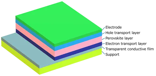
Figure 1. Typical Layer Structure of a Perovskite Solar Cell
The following section examines representative conductive bonding materials that can be used to connect and form external current-collecting electrodes for film-type perovskite solar cells. The advantages and disadvantages of conductive tape, anisotropic conductive film (ACF), and conductive adhesives are considered in terms of their bonding mechanisms, electrical conductivity, and ease of processing.
Conductive tape is a versatile material used, for example, to secure samples during electron microscope observation. An adhesive is applied to a conductive metal foil substrate such as copper or aluminum, allowing electrical conductivity to be obtained simply by attaching the tape. Figure 2 shows a typical cross-sectional structure of conductive tape.
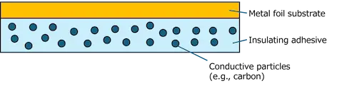
Figure 2. Typical Cross-Sectional Structure of Conductive Tape
Because the metal foil substrate of conductive tape can itself be used as an external current-collecting electrode, this method makes it easy to form an electrode at room temperature. It is also flexible because it uses a thin metal foil substrate and a low-modulus adhesive, allowing it to follow bending of supporting films such as PET. On the other hand, because the adhesive is an insulating material, conductive particles such as carbon may be mixed in to assist conductivity, but sufficient conductivity is not always obtained (Figure 3). Conductivity can also vary depending on the pressure applied when pressing the tape, making it difficult to maintain consistently low resistance.
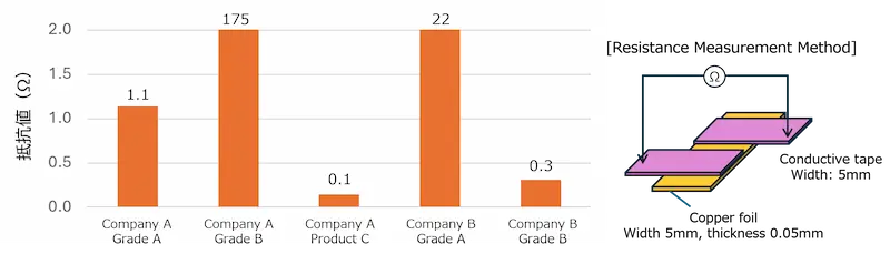
Figure 3. Resistance Measurement Results for Commercially Available Conductive Tapes
ACF is produced by dispersing conductive particles in a thermosetting epoxy resin and processing the material into film form. It already has an extensive market track record for electrically connecting electrodes between displays and circuit boards. Because connections can be formed by short-time thermocompression bonding, productivity is high. However, ACF provides anisotropic conductive connection, conducting only in the vertical compression direction while remaining insulating in the horizontal direction. Figure 4 shows the cross-sectional structure when ACF is used. In film-type perovskite solar cells, ACF can be used to thermocompression-bond electrode materials such as tab wires to a transparent conductive film, thereby forming external current-collecting electrodes.
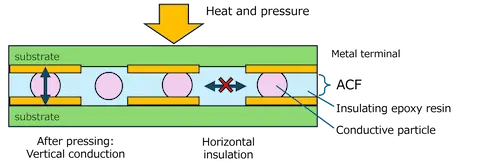
Figure 4. Cross-Sectional Structure and Conduction Mechanism Using ACF
For perovskite solar cells, it is desirable to obtain low-resistance conduction from the entire surface of the transparent conductive film to the external current-collecting electrode so that generated current can be transmitted efficiently. However, as shown in Figure 4, anisotropic conductive ACF contains relatively few conductive particles, resulting in fewer conductive paths and raising concerns that resistance between the transparent conductive film surface and the external electrode may become high. In addition, the typical heating temperature for ACF is around 150°C, which may damage supporting films such as PET even when the heating time is short.
Finally, conductive adhesives are considered. Conductive adhesives are made by mixing conductive particles into adhesives based on epoxy or acrylic resin. During heat curing, shrinkage causes the conductive particles to contact one another, forming conductive paths and allowing current to flow2). Figure 5 shows the general relationship between the volume fraction of conductive particles and electrical resistance in a conductive adhesive. Once the conductive-particle content exceeds the threshold at which the particles contact one another, resistance drops sharply. Conductive particles must therefore be blended at a level above this threshold.
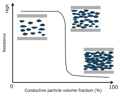
Figure 5. Schematic Relationship Between Conductive Particle Volume Fraction and Electrical Resistance in Conductive Adhesives
Conductive adhesives require no applied pressure and can provide isotropic conductive connections, making it possible to connect current-collecting electrode materials such as tab wires to transparent conductive films with low resistance and form external electrodes. However, because the material is liquid during application, the current-collecting electrode material must be held in place while the adhesive is heat-cured, making the process more complicated. There are also many challenges in applying this method to the roll-to-roll processes being considered for film-type perovskite solar cells. Even with sheet-by-sheet processing, the entire module must be placed in a heating furnace, raising concerns about thermal effects on the perovskite layer.
Table 1 summarizes the comparison of these processes.
Table 1. Comparison of Conductive Connection Processes Applicable to Film-Type Perovskite Solar Cell Modules
| Conductive Tape | Anisotropic Conductive Film (ACF) |
Conductive Adhesive (Thermosetting Type) |
Soldering | |
|---|---|---|---|---|
| Thermal Deformation | ◎ | × | △$2013○ | × |
| Flexibility | ◎ | ○ | × | × |
| Electrical Conductivity | × | △ | ◎ | ◎ |
| Thinness | ○ | △ | ○ | × |
| Number of Process Steps | ◎ | △$2013○ | × | △ |
| Characteristics | Good workability, but conductivity is unstable |
Conductivity is an issue; heating temperature is high |
Good conductivity, but heating is required and workability is poor |
Good conductivity, but the temperature is too high for use with films |
As described above, conventional technologies all present challenges when used to form external current-collecting electrodes for film-type perovskite solar cells, creating a need for an optimal material and process. We offer TK Paste, a distinctive conductive adhesive that uses our proprietary specially shaped silver powder, TK Silver Powder. Applying this technology, we developed the Low-Temperature Thermocompression-Bonding Electrode: TKS Sheet (hereinafter, TKS Sheet), which enables conductive bonding at low temperatures.
Commonly known silver powders include spherical (granular) silver powder and flake silver powder produced by physically crushing spherical silver particles. As shown in Figure 6, TK Silver Powder has an extremely wide variety of structures, including aggregates of radially extending dendrites. Using our proprietary TK Silver Powder manufacturing technology, we can not only create such structures as desired, but also produce large quantities with uniform particle sizes.
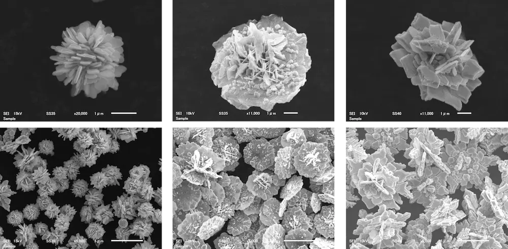
Figure 6. TK Silver Powder with Various Structures
Recent studies have shown that conductive particles with complex shapes such as TK Silver Powder can readily form conductive paths inside conductive adhesives even at low loading levels3). By utilizing this TK Silver Powder, we are developing conductive adhesives with a distinctive capability to provide electrical conduction at low silver content (Figure 7)4).
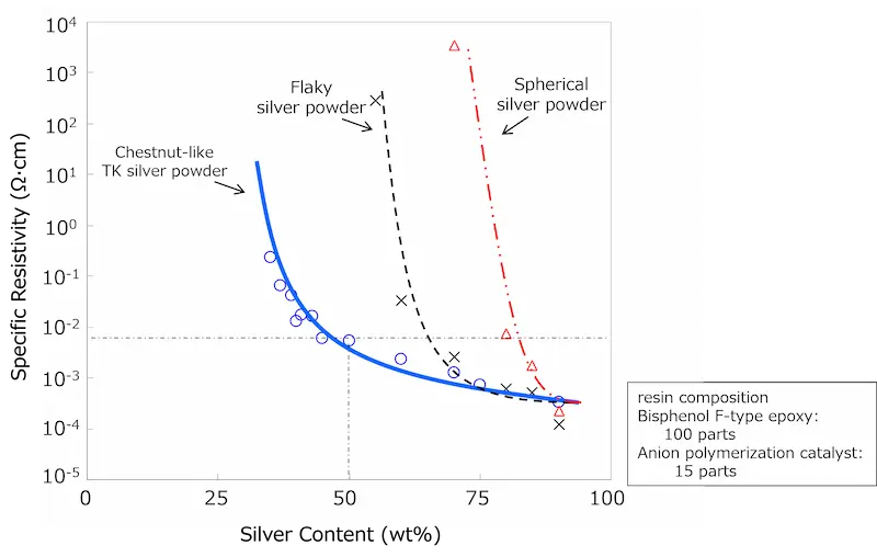
Figure 7. Relationship Between Silver Content and Volume Resistivity for Different Silver Powder Shapes
TKS Sheet is produced by applying and drying a conductive paste containing TK Silver Powder dispersed in a flexible thermoplastic resin onto metal foil such as copper to form a coating layer. It can be easily bonded to adherends such as PET film by thermocompression bonding at approximately 100$2013110°C (Figure 8). TKS Sheet uses large flake-shaped TK Silver Powder with a high aspect ratio, as shown in Figure 9. This large flake silver powder has a particle size of 15$201320 μm, a thickness of 0.1 μm or less, and fine surface irregularities.
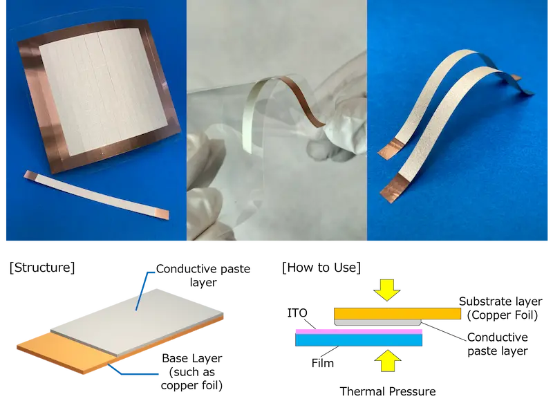
Figure 8. Low-Temperature Thermocompression-Bonding Electrode: TKS Sheet
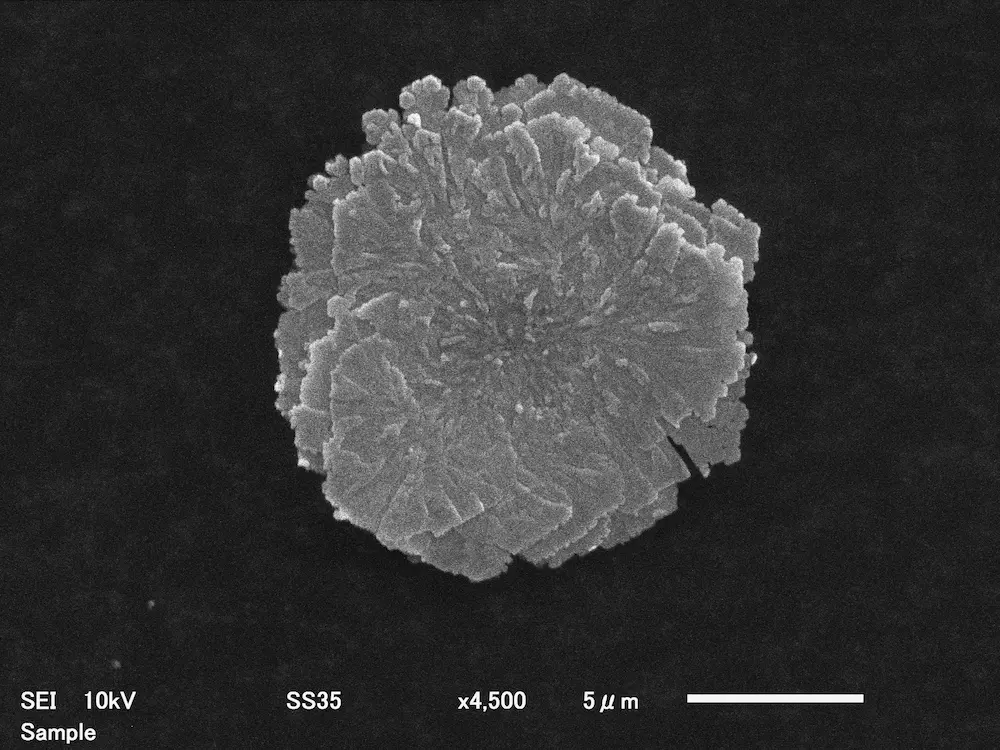
Figure 9. Large Flake-Shaped TK Silver Powder
Figure 10(a) shows an SEM image of the coating surface of TKS Sheet containing this large flake-shaped silver powder, while Figure 10(b) shows a cross-sectional image after thermocompression bonding. As shown in Figure 10(a), the fine surface irregularities of the large flake-shaped silver powder are well exposed at the coating surface and create many contact points with the adherend, helping reduce the resistance at the bonding interface. In addition, the cross-sectional observation after thermocompression bonding in Figure 10(b) shows that the large flake-shaped silver particles are oriented and stacked in multiple layers within the adhesive layer. This ensures contact between silver particles and provides good isotropic electrical connection from the adherend surface to the external current-collecting electrode.
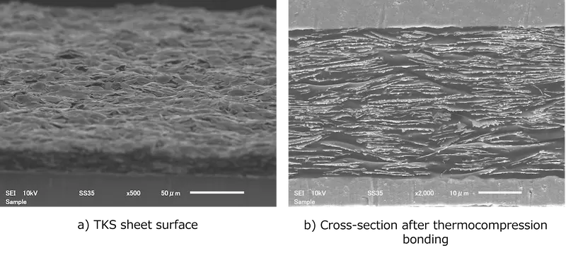
Figure 10. Surface and Cross-Sectional Observations of TKS Sheet After Thermocompression Bonding
Furthermore, because the silver particles have a high aspect ratio and are stacked in an oriented configuration, horizontal deformation such as bending or stretching of the adhesive layer has little effect on the contact points between silver particles, as shown in Figure 11. As a result, the change in conductivity remains small even when TKS Sheet is bonded to a flexible film.
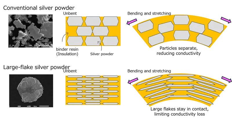
Figure 11. Effect of Horizontal Stretching
This section presents an example of forming an external current-collecting electrode for a film-type perovskite solar cell using TKS Sheet. Figure 12 shows an example in which current-collecting electrode wiring is formed on ITO-PET film using a TKS Sheet 300 mm long and 10 mm wide. Although no perovskite solar cell was formed on the ITO-PET film shown in Figure 12, the sample was produced to simulate a case in which a busbar is attached across the full width of an edge electrode to assist conduction in a large perovskite solar cell module. The metal foil used for the TKS Sheet was C1020-H copper with a thickness of 0.05 mm. The coated surface was thermocompression-bonded to the ITO-PET film at 110°C and 2 MPa for 2 minutes. No deformation of the ITO-PET film was observed after thermocompression bonding, and no cracking or delamination occurred when the film was bent (Figure 13). In this way, TKS Sheet can form a flexible external current-collecting electrode simply by thermocompression bonding directly onto the surface of a transparent conductive film. We propose a method in which the metal foil of TKS Sheet serves as the current-collecting electrode and wiring is connected by soldering or connectors, allowing current to be extracted from large film-type perovskite solar cells. Evaluation by multiple perovskite solar cell manufacturers is currently underway.
|
|
|
In establishing a process for forming external current-collecting electrodes on film-type perovskite solar cells using TKS Sheet, we are developing not only conductive pastes and sheets but also thermocompression-bonding methods capable of applying appropriate pressure and temperature. For roll-to-roll processes, which are expected to reduce costs, we are also considering supplying reel-form thermocompression-bonding electrodes produced by applying conductive paste to long metal foil.
At present, our laboratory is equipped to produce TKS Sheets according to the shape and size of perovskite solar cells and to attach them to actual modules using the thermocompression-bonding equipment we developed (Figure 14). We are supporting development projects involving perovskite solar cells and their applied products. Going forward, we aim to develop equipment capable of supporting mass production and larger-scale products in cooperation with equipment manufacturers.
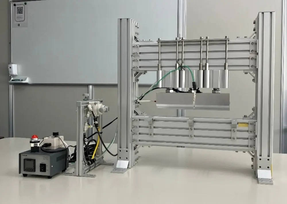
Figure 14. Developed Thermocompression-Bonding Equipment
In response to the COP28 goal of tripling global renewable energy generation capacity by 2030, Japan has set a target of 36$201338% for the share of renewable energy in its electricity generation mix5). Solar power is expected to account for the largest share among these technologies, at approximately 14$201316%.
Japan is said to have many companies with advanced functional-film technologies and to be taking the lead in the development of film-type perovskite solar cells6). Japan also has one of the highest levels of installed solar power capacity per unit of flat land among major countries. Because securing additional installation sites within Japan's limited land area is difficult, film-type perovskite solar cells, which weigh approximately one-tenth as much as silicon-based solar cells, are considered promising for installation on building walls, roofs with low load-bearing capacity, and other locations where conventional solar panels could not previously be installed.
As research into perovskite-layer materials and coating methods advances and practical implementation draws near, development of downstream processes for assembling solar cells into modules is accelerating. We will continue developing our low-temperature thermocompression-bonding electrodes as materials that can contribute to improved solar cell performance and the creation of clean energy.
Layer Materials, Film-Formation Processes, and Device Design for Improving the Durability, Stability, and Power Generation Efficiency of Perovskite Solar Cells, AndTech, Inc., published July 31, 2026.
| Please be as specific as possible in your inquiry. Depending on the contents of your inquiry, it may take some time for us to reply to you. If you need product documentation (SDS/safety data sheets, TDS, instruction manuals, etc.), please contact us via “Request for SDS and other product documentation” ※Sales message through the inquiry form are strictly prohibited. |
KAKEN TECH, MICROCLEANER, MICROCLEAN&MARKLESS and MARKLESS are trademarks of KAKEN TECH CO., LTD. in PRC.
KAKEN TECH is a trademark of KAKEN TECH CO., LTD. in the U.S..
 Inquiry form