- Company
- Products
- Technical report
- Indusrial cleaning
- Micro Joining and Assembly Technology
- Ultrasonic technology
- Trouble solution
- Cleaning
- Removing
- Attaching
- PCB Columns
Published on :
Section 2 PCB Packaging Equipment
Cleaning equipment
Yuki Akamatsu, Research and Development Department, KAKEN Tech
Cleaning is an operation to separate and remove the unnecessary –tarnish- attached on the object to the level where the object is able to express and maintain its original characteristics and quality. Although dry washing methods of not using liquid also exist, here we refer to wet cleaning methods using cleaning chemicals as “cleaning” in this article.
Besides, cleaning equipment in production line is a machine that realizes the most appropriately designed cleaning process by effectively bringing out physical chemistry functions of cleaning chemicals including wetting, soaking, solving, peeling, diffusing, and separating, to tarnish in order to achieve the sufficient quality of the object and enable smooth production.
Therefore, designing or introducing cleaning equipment must be carried out based on the clear understanding about the quality requirements with thorough research on the property of the tarnish, object and cleaning chemicals as well as on the shape of the tarnish and the characteristics of the targeted object. Especially PCBs with high quality standards call for the individual design of cleaning process. Many cases indicate that hastily introducing generally designed cleaning equipment, even used with proven cleaning chemicals, usually ends up in failure in securing the necessary quality. Although some may misunderstand with these cases that “cleaning process rather causes quality deterioration,” it all comes down to underestimating the significance of cleaning process design.
The first half explains the basics in designing deflux process and the latter half demonstrates the proven cleaning system in packaging line and gives existing examples of cleaning quality control.
This article opts out the descriptions of flux residue, the target of cleaning, and deflux chemicals introduced in Section 6.2, Chapter 3. Instead, the following will explain the cleaning process given that the most suitable cleaning chemicals are chosen.
Cleaning process is a process to efficiently separate flux residue from the object by wetting, soaking, solving, peeling or diffusing with cleaning chemicals.
Although simply soaking the object in cleaning chemicals could remove flux residue, it takes too much time to complete the removal, thus failing to suit the production aim. The first step of cleaning process design is to shorten the cleaning time with the raised cleaning chemicals temperature or with the physical functions such as liquid flow or ultrasonic. Also, equipment design is essential in accordance with the packaging structure of the object to equalize the cleaning quality, based on the clear understanding on controlling factors of cleaning process.
Cleaning speed has an impact on the solving rate and diffusion velocity of flux residue solved in cleaning chemicals. The dissolvability of residual flux highly depends on the cleaning chemicals. Diffusion velocity is the key to maintain the dissolubility of cleaning chemicals and to accelerate the cleaning speed
Below is the Fick’s first law, the principle on diffusion;
dm/dt = -D*A*dc/dx
D: Diffusion coefficient
(Minus: Diffusion happens toward lower concentration.)
Fick’s first law states that dm, material mass that diffuses toward direction x across square measure A in the time period of dt, goes in proportion to dc/dx, the concentration gradient on the two-dimension. 1
In other words,
Diffusion velocity = Diffusion coefficient *Concentration gradient,
and since diffusion velocity reflects the value of concentration gradient, maintaining high concentration gradient promotes the liquid replacement on the contact surface to accelerate the cleaning speed.
Cleaning equipment has two methods to replace the liquid on the contact surface with liquid flow in a short period of time in order to increase the diffusion velocity: one is the circulating jet method that circulates the liquid in the cleaning tanks with pumps and the other is the direct path cleaning method that cleaning chemicals, forced from one direction, directly flushes through the gap between objects, utilizing the entire energy of discharge and intake from the pumps.
Direct path cleaning method improves the cleaning efficiency between gaps by gathering the objects to narrow the space the liquid can go through, resulting in flow speed acceleration. 2 Substrates that require narrow gap cleaning, for Flip Chip packaging being one, or those that are relatively flat prefer this method. On the other hand, for PCBs with intricate surfaces mounted with various components, methods in which turbulence from many directions creates a surface flow, such as the circulating jet method, are preferable to level the cleaning performance. Also, the direct path cleaning method demands several special baskets that suit the shape of each cleaning object when cleaning high variety low-volume products.
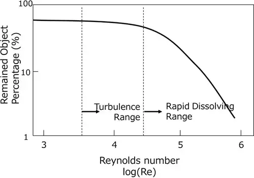
In the circulating jet method turbulence enhances the cleaning efficiency, yet the turning point in cleaning effect appears far above the critical Reynolds number, where Re= more than 26,000. (Fig. 2.8.1) Circulation amount and speed need to be determined to satisfy the appropriate Reynolds number range to get the turbulence effect.
The essence of deflux is the removal of flux residue on the surface, ionic residue, and residual flux under the electronic components that are difficult to conduct visual inspection. As recent Flip Chip packaging represents, those with gaps of less than 50um under the components have been produced and the gaps will be even narrower considering the trend. Deflux is becoming more difficult because of smaller apertures where cleaning chemicals contact flux residue under the electronic components. Cleaning difficulty varies depending on the size and shapes of the components granting the same solder paste and under the same conditions of reflowed flux residue. Deflux of PCBs that have complex surfaces mounted with various components require the most suitable condition setting for the packaging component with the longest cleaning time. Especially the space under the components needs higher performance settings since the cleaning quality cannot be verified unless post-cleaning destructive inspection is conducted. For such settings to be determined precise evaluation on quality discrepancy becomes necessary based on the quantitative assessment on cleaning speed.
While aforementioned diffusion velocity largely influences conventional deflux of circuit surfaces, for under electronic components it is dissolvable velocity that has a large impact. Although diffusion and dissolvable velocity have different mechanisms, the following form similar to Arrheniusu equation can describe both D the diffusion coefficient and k the rate constant for dissolution kinetics equation; 3
D=A exp(-E/RT)
K=A exp(-E/RT)
D: diffusion coefficient
A: temperature irrelevant constant (frequency factor)
E: activation energy (Arrhenius parameter)
R: gas constant
T: absolute temperature
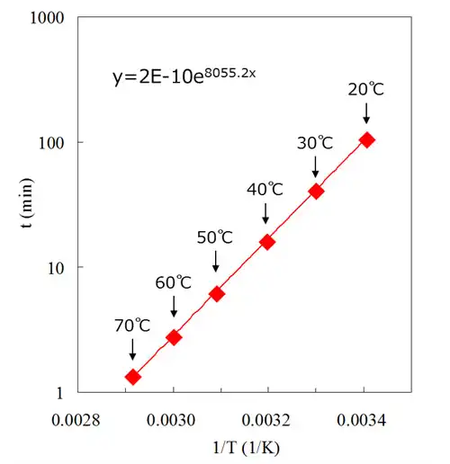
As the above equation shows, the higher the cleaning temperature becomes, the shorter the cleaning time due to proportionately higher D and k. Additionally, when dissolving solid flux residue the raised temperature softens the residue giving the surface fluid effect.
Fig. 2.8.2 shows the relation between cleaning temperature and dissolving time of flux residue for lead-free solder paste. Cleaning time assessment enables calculation on cleaning speed given the same physical/mechanical conditions.
System design is necessary in deflux process based on cleaning method thermodynamics as well as choosing highly dissolvable cleaning chemicals. As shown in Table 2.8.1 listing features/advantages and disadvantages of common deflux methods, choosing appropriate cleaning chemicals and methods are essential in securing the precision cleaning quality.
| Classification | Name | Features/Advantages | Disadvantages |
|---|---|---|---|
| Immersible Cleaning | Jet Circulation Cleaning |
Liquid circulates in cleaning tanks with pumps, diffusing the object. Changing the liquid transfer pressure of the pump or the shape of outlet can improve the cleaning performance. Less physical impact on the products. |
Liquid circulates in cleaning tanks with pumps, diffusing the object. Changing the liquid transfer pressure of the pump or the shape of outlet can improve the cleaning performance. Less physical impact on the products. Cleaning performance may be inconsistent depending on the fixed position of the products in tanks. Lower cleaning performance in narrow gaps. |
| Direct Path Cleaning | The method to directly pass a large amount of cleaning chemicals through the products by reducing the gap with products or jigs. Suitable for cleaning gaps because it can efficiently send the suction/discharge energy of pumps to the products. |
It may not be effective depending on the product shape, for that the products must be gathered in cleaning baskets. Basket alteration is also necessary. Unsuitable for high-variety low-volume product cleaning. Mostly large-scale. |
|
| Ultrasonic Cleaning | Cleaning with the cavitation function occuring from ultrasonic radiated in cleaning chemicals. It promotes peeling and diffusing the object from the products. Suitable for cleaning narrow gaps and removing solder balls and small particles. |
To secure the cleaning performance consistency, oscillation of products is necessary to equalize the cavitaion effect in cleaning tanks. Since ultrasonic has a property of going straightforward, its effect weakens on lapped products. Some components are not applicable because soft materials such as alminum may cause errosion. Cleaning performance improves with deaerated cleaning chemicals. |
|
| Vacuum Cleaning (Depressurizing Cleaning) |
Depressurizing the inside of confined containers, containing the products soaked in cleaning chemicals, lead cleaning chemicals to enter between deaerated gaps of the products. Suitable for cleaning complicated shaped products. Better performance with ultrasonic cleaning. |
Facility costs relatively expensive. Longer cleaning time due to repeating the state with an ambient pressure and that of depressurized. Cleaning performance depends on the confinement state. |
|
| Non-Immersible Cleaning | Showering Cleaning | The method to clean a wide range with a small amount of cleaning chemicals by showering the chemicals with a low pressure from nozzles. Either line several nozzles or move them around to cover wider area of cleaning. |
Unsuitable for cleaning chemicals with high formability or high flammability. Showering must thoroughly cover the entire area to gain a satisfactory effect. |
| Jet Spraying Cleaning | This method is to remove the object attached on the product surface by jet spraying the cleaning chemicals from nozzles with a higher pressure than showering, utilizing the collision force of liquid. |
Unsuitable for cleaning chemicals with high formability or high flammability. Spraying must thoroughly cover the entire area to gain a satisfactory effect. |
|
| Vapor Cleaning | This method is to remove the object attached on the product surface with vaporated cleaning chemicals condensed on the surface. Same effect as to rinse with purified distilled liquid. Used for finishing cleaning. Can also dry if the product taken out when its surface temperature equals to the vapor temperature. |
Explosion-proof facilities are necessary when using cleaning chemicals with a low flash point. Cooling pipes in the upper area of cleaning tanks are also necessary to prevent solvent vapor loss. Unsuitable for objects with low heat capacity. |
Many of deflux chemicals used in packaging process have the boiling point of over 200 C, unrealistic to dry out on their own. There comes in the rinse process where fresh rinse chemicals, such as water that has the high capability to dry and remove ionic substances or water content alcohol, dissolve and diffuse cleaning chemicals with a high boiling point and high flux density, ultimately replacing the cleaning chemicals.
In the rinse process of mass cleaning, problems including rinse property deterioration, flux residue reattachment to the cleaning object, drying failure or tarnish remain after drying process may arise because of the increasing concentration of cleaning chemicals and flux residue in rinse chemicals constantly brought in from cleaning tanks. Therefore rinse process in precision cleaning such as for PCBs usually has several tanks, gradually rinsing off the cleaning chemicals and flux residue. Despite the cleaning process succeeds in residual flux removal, cleaning performance will deteriorate if contamination concentration is not controlled properly in the finishing rinse process. Thus it is important to control and operate the system by always monitoring the contamination concentration of the finishing rinse tank that it remains below the set limit based on the required quality of the object.
The following lists the necessary control conditions in rinse process;
Conductivity is commonly used as a control standard for the finishing rinse tank since flux residue contains a large amount of ionic substances came from the activator such as amine halide salt and organic acid. The more ionic substances contained, the higher the conductivity becomes. Thus rinse chemicals contamination can be controlled by monitoring the conductivity transition in water or water content alcohol.
Generally water with the conductivity of 20uS/cm or higher may cause metal discolor or corrosion because of the electric chemical reaction. Also, it accelerates ionic surfactant precipitation, causing reattachment of unsolved or slightly solved flux residue compounds solubilized or spread in water because of ionic surfactant. 5
Water content alcohol, on the other hand, has mere possibility of metal rust or corrosion because alcohol molecules form a cluster structure surrounding water molecules in alcohol without generating H+ ion that accounts for metal rust and corrosion. In addition, unsolved or nearly unsolved flux residue is less likely to reattach for it is soluble to alcohol. 6
Yet the most important in post-precision cleaning quality is to maintain the circuit characteristics as well as to prevent corrosion or reattachment on the surface, asking for the conductivity setting appropriate for required cleaning quality.
When rinsing with water, conductivity increases to cause metal corrosion as water resistivity decreases in inverse proportion to water temperature rise.
Water content alcohol that contains water of 40 weight percent or more, though nonhazardous under the Fire Services Act, has a flash point as to drinkable alcohol such as whisky, requiring chillers in order to maintain the liquid temperature below its flash point.
Either with water or water content alcohol, quality discrepancy such as drying failure and post-cleaning tarnish arises as the concentration of cleaning chemicals and flux residue increases in the finishing rinse tank. Accordingly designing the most suitable equipment for long-term operation including the recycle and retrieval process is of the essence, based on the trial calculation of material balance in cleaning at the upper limit of contamination concentration for long-term use.
Water content alcohol as rinse calls for water concentration control. Under ordinary use water concentration increases as alcohol with a low boiling point volatilizes. Higher concentration may cause degradation in rinse and drying properties. Refractometer enables water concentration control.
Properties and shapes of cleaning objects largely influence the drying process in wet cleaning, which prefers higher vapor pressure to vaporize rinse chemicals attached to the object.
Drying methods consist of sole or a combination of below-listed physical methods;
(1) Drying methods consist of sole or a combination of below-listed physical methods;(1) To accelerate vaporization by replacing the rinse vapor containing gas around the cleaning object with fresh gas, lowering the rinse vapor concentration. E.g. air circulation and blowing
(2) To promote vaporization by heating rinse chemicals attached to the object and elevating vapor pressure of rinse chemicals. E.g. air circulation
(3) To separate rinse chemicals from the object by physical force. E.g. suction dry, spin dry
(4) To accelerate vaporization by depressurizing the atmosphere around the object lower than the vapor pressure of rinse chemicals. E.g. vacuum dry
(5) To dry the object in saturated vapor, using solvents with low vaporization heat to replace and dry. E.g. vapor dry
In PCB deflux, heat transfer speed of the object often determines the drying process since attached amount of rinse chemicals is relatively little compared to the size of the object. PCBs contain a large amount of resin materials as insulator including epoxy resin, polyimide resin and Tefron resin, requiring an equipment design that enhances the heat transfer speed of these substances.
Fourier’s law, the principle of heat transfer, can be written as follows in the same form as aforementioned Fick’s first law, in which dq/dt, the amount of heat transfer per unit time, proportions to A, square measure of the material vertical to the heat direction, and dT/dx, the temperature gradient of the heat direction; 7
dq/dt= - λ*A*dT/dx
λ: thermal conductivity
As Table 2.8.2 of thermal conductivity of each material shows, the thermal conductivity of resin materials including epoxy resin is less than one percent compared to that of metals. Hence, heat transfer speed escalation with forced convection of air as a medium for heat transfer is necessary in PCB drying process.
Air circulation drying needs the most appropriate value setting on wind speed and wind amount based on the experiments. Vacuum drying requires measures to increase heat transfer speed by utilizing heat transfer of radiation and conduction since air convection will not occur.
| Substance | κ (W/m*C) |
| Silver | 420 |
| Copper | 398 |
| Gold | 320 |
| Alminum | 236 |
| Steel | 86 |
| Tin | 65 |
| Lead | 35 |
| Alumina | 21 |
| Stainless Steel | 18 |
| Lead Glass | 0.6 |
| Teflon | 0.5 |
| Polyethylene | 0.4 |
| Sylicon | 0.2 |
| Epoxy Resin (Bisphenol A) | 0.2 |
Cleaning equipment must operate where the contamination concentration of cleaning chemicals and rinse chemicals is always below the control standards given the control standards on the cleaning equipment. Since flux residue and foreign materials contaminate the next process by reattaching to the object surfaces, consistent cleaning performance in long-term continuous use only realizes without a structure to retrieve the contamination and purify the cleaning and rinse chemicals. The retrieval and purification structure plays an important role in the cleaning system, greatly influencing the running costs and environmental burdens as well as the cleaning performance.
Common retrieval and purification structures are as follows;
This method is to collect solid foreign materials by filtering, including solder balls, separated compounds of flux residue and substrate scrap mixed in cleaning and rinse chemicals, or to retrieve ionic substances and organic compounds solubilized or spread in rinse chemicals by adsorption.
Non-woven filters made of resin collect solid foreign materials such as solder balls, with apertures based on the size of collecting objects. Filtering has two ways: one is dead end filtration installed in the circulation line of equipment and the other is by-pass filtration. While the former can filter the entire amount of liquid, depending on the aperture size and collectability it may degrade the performance of pumps and the cleaning system by clogging the liquid flow with greater pressure loss. The latter, though such concern is less likely to apply, requires the eligible choice of pumps considering the liquid residence time.
Also, filters adsorb ionic substances solubilized or spread in rinse chemicals with ion exchange resins and organic compounds with activated carbons. As mentioned above, especially the water for rinse is apt to cause metal corrosion or reattachment of flux residue due to high conductivity caused by the elevated ionic substances concentration. Organic compounds, too, if mixed a large amount trigger drying failure or tarnish. Filtering prevent these problems, contributing to the longer lifetime of rinse chemicals.
However, filters need to be changed periodically because they have a limit in absorption.
When using water for rinse, settled or mechanical separation in a different tank from the rinse tank can separate and retrieve the oil compounds of cleaning chemicals and of flux residue that deteriorates the rinse property from the rinse water. The oil removed water, recycled as pre-rinse water, can mitigate the burden of water waste on the cleaning system. However, some kinds of cleaning chemicals preclude oil/water separation.
Distillation is common for cleaning chemicals purification in the one liquid cleaning system such as hydrocarbon based cleaning chemicals. It secures a consistent cleaning performance by retrieving nonvolatile flux residue to maintain the low concentration of flux residue in cleaning chemicals. Conventionally, cleaning chemicals applicable to continuous distillation supposedly consist of a simple compound or azeotrope, while mixed solvents with several different boiling points have been distilled per batch. Moreover, only non-water containing solvents have been considered for distillation since water may cause explosive boil due to boiling point difference and imbalance of vapor-liquid equilibrium in distillation.
Most of deflux chemicals suitable for removing flux residue, the mixture of various polar compounds, did not fit into these categories for continuous distillation. However recently the newly suggested cleaning system has solved this issue with a continuous distillation structure for deflux chemicals such as non-azeotropy solvents and water content solvents. 8
In the cleaning system where water content alcohol acts as rinse, continuous distillation retrieves nonvolatile flux residue and cleaning chemicals with a high boiling point. Distillation maintains the consistent rinse property and high purity of liquid in the finishing rinse tank. Since water content alcohol is non azeoropy which water and alcohol have different vapor pressure, knowhow of the equipment manufacturers is necessary to install continuous distillation with a component ratio consistency based on thorough understandings on vapor-liquid equilibrium.
The followings are the structures of commonly used deflux system in packaging line (Fig. 2.8.3);
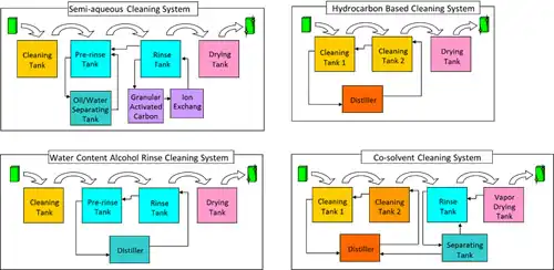
The system with cleaning chemicals mainly composed of glycol ether in addition to surfactant and water, and rinse water. The basic tank structure has four tanks for cleaning, pre-rinsing, rinsing and drying (the number of cleaning or rinse tank may increase if necessary). Attached are the granular activated carbon and ion exchange facilities to maintain the purity of rinse water, and ultraviolet disinfection equipment to prevent microbe contamination of various germs. Drain facilities are also necessary, contributing to the upsizing of cleaning equipment. Though not all cleaning chemicals apply, oil/water separation facilities can mitigate the burden of water waste on the cleaning system. Cleaning chemicals contain VOCs, yet the compounds will not volatilize when drying because of rinse water.
The system with cleaning chemicals mainly composed of glycol ether or higher alcohol, and water content alcohol for rinse. The basic tank structure is the same as that of quasi-water cleaning system. The difference is the great amount of reduction in waste liquid because rinse chemicals regenerate through continuous distillation. Cleaning performance remains consistent because of clean rinse chemicals in the finishing rinse tank, where distillation and ion exchange resins cut the contamination. The sterilization of water content alcohol and distillation together eliminate the necessity of microbe disinfection and drain facilities, realizing smaller cleaning equipment with lesser supplement facilities compared to quasi-water cleaning system.
Either the system with hydrocarbon based cleaning chemicals and IPA rinsing in order to secure ionic substance removability, or the one liquid cleaning system with hydrocarbon and glycol ether combined.
The latter is more popularly used with the basic structure of three tanks: pre-cleaning, cleaning and drying, many attached with a distiller. Cleaning chemicals with a relatively low boiling point suitable for the one liquid cleaning system requires adequate safety measurements such as explosion-proof facilities.
The system with cleaning chemicals mainly composed of hydrocarbon or glycol ether based solvents, and fast-drying, nonflammable fluorine solvents for rinse. Although this system uses less heat in drying, the VOCs consisting 100% of cleaning chemicals largely impact the environment in an open system and fluorine solvents are expensive. Therefore closed system is popular to reduce atmospheric exhaust.
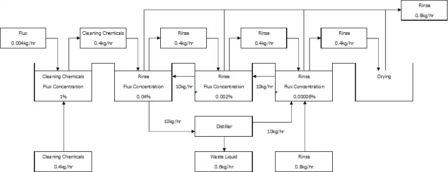
Here describes the examples of cleaning quality control on deflux equipment capable of continuously distilling rinse chemicals (Fig.2.8.4) using glycol ether based cleaning chemicals and water content alcoholic rinse chemicals as follows;
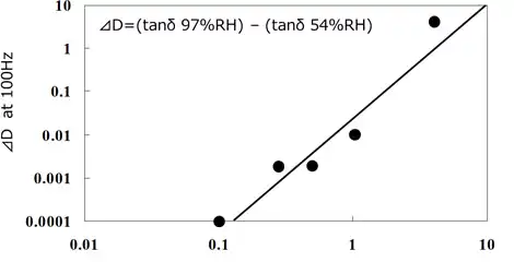
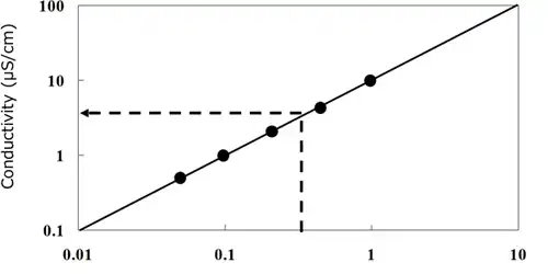
Based on the control standard of dielectric loss (tanδ) of electrode surfaces measured with JIS2 type interdigitated array electrodes, deflux equipment determines the concentration of flux residue contamination and of rinse chemicals in correlation to tanδ of electrodes (Fig 2.8.5). Also packaging sites design the equipment capable of rinse chemicals concentration control with a conductivity meter based on the correlation of contaminating flux residue concentration and conductivity (Fig.2.8.6).
Mass cleaning, which constantly cleans a great deal of work, prioritizes the most appropriate equipment design including the concentration control of the finishing rinse tank and recycling, with calculations on the material balance of cleaning at the upper limit of tarnish concentration in long-term use.
As Fig 2.8.7, the flow of deflux cleaning, shows, clarification of control standards on the cleaning performance enables optimization of each process.
Ideal deflux equipment realizes high cleaning performance, high production efficiency and low environmental impacts. Additionally, it must respond to requests from the packaging scene including downsizing of the equipment and costs, efficient cleaning methods with lesser amount of cleaning chemicals, recycling system and closed system of entire equipment.
To satisfy these requests, building and designing a cleaning system is of the essence with which post-cleaning reliability evaluation technology, cleaning chemicals design technology and cleaning equipment design technology all combined and collaborated.
Yuki Akamatsu
1)D.J.SHAW, translated by Fumio Kitahara and Koichiro Aoki, Chemistry on Colloid and Surface (Hirokawa Bookstore, 1978), 21.
2)Junichi Maeno, Production Technology Application Manual (Kogyo Chosakai Publishing, 2000), 865.
3)Gordon M. Barrow, translated by Ryoichi Fujishiro, Physical Chemistry (Tokyo Chemistry Doujin Publishing, 1981) 644.
4)Yutaka Hiratsuka, Ready-to-use Cleaning Technology (Kogyo Chosakai Publishing, 2001) 33.
5)Junichi Maeno, Industrial Cleaning No. 5 (2010), 12.
6)Shigeo Hori, Ready-to-use Cleaning Technology (Kogyo Chosakai Publishing, 2001) 335.
7)Shigefumi Fujita, Chemical Engineering I (Iwanami Publishing, 1977) 50.
8)Yuki Akamatsu, Electronic Materials, July edition, supplement (2009) 90.
9)Shigeo Hori, Hisakazu Takahashi, Surface Mount Technology, Sep. edition, (1983), 30.
10)Hisakazu Takahashi, Production Technology Application Manual (Kogyo Chosakai Publishing, 2000) 859.
 |
Trouble solution
|
|---|---|
 |
Technial report
|
 |
Technial report
|
| Please be as specific as possible in your inquiry. Depending on the contents of your inquiry, it may take some time for us to reply to you. If you need product documentation (SDS/safety data sheets, TDS, instruction manuals, etc.), please contact us via “Request for SDS and other product documentation” ※Sales message through the inquiry form are strictly prohibited. |
KAKEN TECH, MICROCLEANER, MICROCLEAN&MARKLESS and MARKLESS are trademarks of KAKEN TECH CO., LTD. in PRC.
KAKEN TECH is a trademark of KAKEN TECH CO., LTD. in the U.S..
