- Company
- Products
- Technical report
- Indusrial cleaning
- Micro Joining and Assembly Technology
- Ultrasonic technology
- Trouble solution
- Cleaning
- Removing
- Attaching
- PCB Columns
Published on :
Mounting (component mounting) in the electronics industry refers to soldering electronic components such as semiconductor devices and IC chips to printed circuit boards and other devices and electrically connecting terminals and wiring to make them ready for operation.Depending on the performance required of the printed circuit board, the mounting process must be selected by considering which electronic components are to be mounted on which printed circuit board and by what method.
The component mounting process is largely divided into the surface mount process and the insertion mount process, and the soldering method used for each differs.
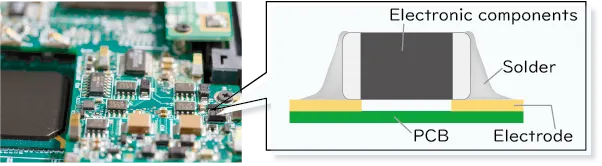
| Surface mounting, also called SMT (abbreviation of Serface Mount Technology), is a method of mounting and soldering the electrodes and leads of electronic components on the connecting electrodes (lands) placed on the surface of a printed circuit board, as shown in the figure below.Reflow soldering method is used for soldering. |
 |
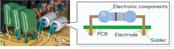
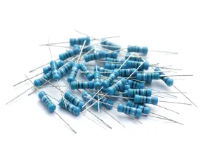
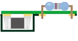
| In insertion mounting, as shown in the figure below, a component with wiring called a lead is inserted into a through-hole on a printed circuit board, and the lead of the component and the electrode (land) around the through-hole are soldered together.Wave soldering method is used for soldering. |
 |
| Examples of Electronic Components | Features | |
|---|---|---|
| Surface mounting process | 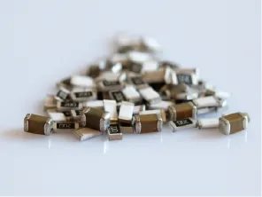 |
🙂 Mounting of small electronic components and miniaturization of circuits become possible, increasing mounting density. 🙂 Automation and downsizing of components will lower costs. |
| 🙁 With miniaturization, manual correction becomes more difficult. 🙁 The joint strength is low because the joint area is very small. 🙁 The reflow soldering process heats up the entire board in the furnace. The entire printed circuit board and components are subjected to thermal stress. | ||
| Insertion mounting | 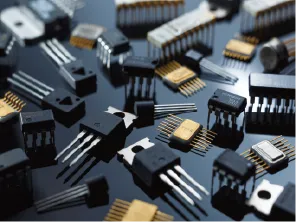 |
🙂 High connection strength due to bending of lead tips when inserting components. 🙂 Only the lead part is heated in the wave soldering process, so there is little thermal effect on the component. |
| 🙁 Large capacitors and oddly shaped parts such as connectors require manual insertion. 🙁 Many large components are used, and the mounting density is lower than that of surface mounting. |
Soldering is the process used to mount electronic components on printed circuit boards. Soldering methods are largely divided into three types: reflow soldering, wave soldering, and manual soldering.
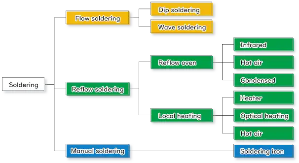
Recent component mounting is done using a combination of the methods shown in the above figure.
For example, local or manual soldering is used for each part when soldering parts that are not heat resistant or have large thermal capacities and cannot pass through the reflow process.
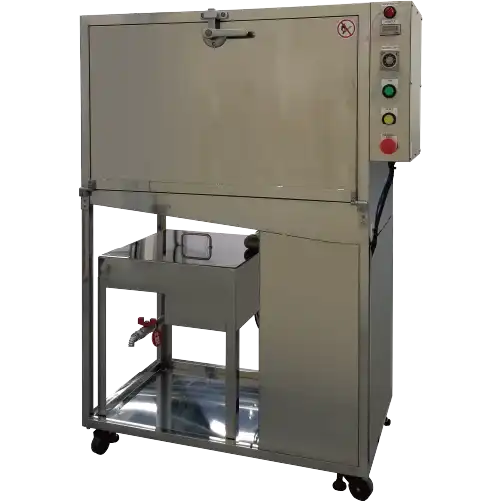
Regardless of the soldering method used, flux cleaning (PCB cleaning) after soldering is effective to improve the reliability of the PCB.KAKEN TECH develops cleaning liquid and cleaning equipment to remove flux residue generated on printed circuit boards. Please feel free to consult with us about cleaning methods according to your soldering method.
We will now explain in detail the differences between reflow and flow soldering and the processes of each method.
Shows the surface mounting process by reflow soldering.
 ①Print solder paste on printed circuit board |
 ②Mounting components |
 ③Soldering in reflow oven |
 ④Flux Cleaning |
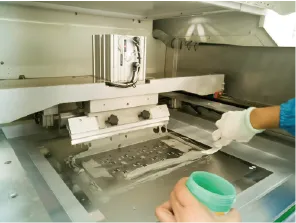 | Although precoating (plating) and solder balls are also available, the most commonly used method is to print solder paste on a printed circuit board using a metal stencil. It is said that "about 70% of product defects in the mounting process are caused by the initial solder paste printing process". Therefore, a process to inspect the amount of solder paste applied and the printed position may be added after printing. Cleaning the metal stencil used for printing is also important to maintain and improve printing accuracy. |
▼▽Solder paste printing process and metal stencil cleaning are explained in the following page!▽▼ | |
 |
PCB Mounting Columns
|
|---|---|
 |
Products information
|
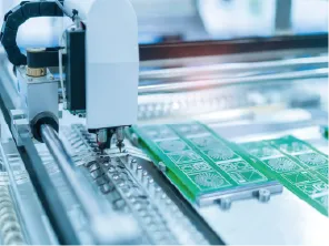 |
Equipment called a mounter is used. The nozzle in the mounter picks up the electronic components on the tape reel or tray and places them at the appropriate position on the printed circuit board. |
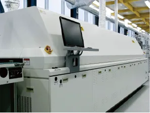 |
The reflow soldering process uses an oven-like device called a reflow oven. The reflow oven has a tunnel-like structure that integrates the three zones of preheating, main heating, and cooling. While the printed circuit board passes through the reflow oven on a conveyor, the heat necessary to melt the solder paste is supplied for soldering. |
| |
|
When soldering, all soldering points must be heated above the melting point of the solder paste and below the heat resistance temperature of the electronic components and printed circuit boards to be mounted. When soldering in a reflow oven, the temperature is controlled according to a "temperature profile" set so that the temperature inside the reflow oven is appropriate for the type of solder paste, mounted components.
For example, if the temperature rises too quickly, the solvent component in the solder paste may boil, resulting in voids or solder balls. Conversely, even if the temperature in the reflow oven is the same, some electronic components may have difficulty in raising the temperature of the bonding area depending on their size and shape, and insufficient heating may result in a decrease in bonding strength. Therefore, it is important to set the temperature profile after checking the characteristics of the solder paste and electronic components.
Heating methods of reflow oven include hot air heating, infrared heating, and steam heating, etc. Some reflow ovens combine multiple heating methods to maintain temperature uniformity inside the oven and prevent over-temperature rise.
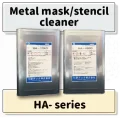
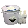
The inside of the reflow oven needs to be cleaned regularly because the heating process causes atomized flux from the solder paste to accumulate inside the oven.
▼▽Cleaning agents for reflow oven are introduced in the following pages.▽▼ | |
 |
Products information
|
|---|---|
 |
After reflow soldering is completed, the PCB is cleaned to remove flux residue (flux cleaning). Flux residue left on PCBs can lead to physical and electrical problems, and flux cleaning is an effective way to prevent and solve such problems. When selecting a cleaning method, it is necessary to understand not only the cleaning performance of flux, but also its environmental impact and safety, the burden on workers (frequent liquid replacement and waste liquid disposal), the impact on the target PCBs and electronic components, running costs, and other advantages and disadvantages. |
| ▼▽Flux cleaning is explained in the following pages!▽▼ | |
 |
Trouble solution
|
|---|---|
We will introduce the insertion mounting process by flow soldering.
 ①Insert components into the PCB. |
 ②Apply flux |
 ③Pass through solder bath and soldered. |
 ④Clean flux |
 |
The lead is bent to match the pitch of the through-hole to be inserted, and the lead of the component is inserted into the through-hole using an automatic insertion machine called an inserter. For stable quality and mounting cost, it is desirable to use components that can be inserted automatically, but if there are special components that cannot be inserted automatically, they are inserted manually at the end of the process. |
 |
Flux can be supplied by
|
▼▽Flux is explained on the following page!▽▼ | |
 |
PCB Mounting Columns
|
|---|---|
| As shown in the figure below, soldering is performed on the leads by passing the printed circuit board over the solder that has been melted at high temperature. The most common specification is to make two waves (peaks) so that the molten solder can easily contact the leads as the PCB passes through. |
 |
| Jet types include jets and waves with varying strengths and heights, and jets with waves that move left and right to make it easier for solder to reach electrodes and through holes and to produce a good finish. |
 |
Many insertion-mounted components to be flow-soldered are not resistant to cleaning agents, and in many cases, only the backside of the printed circuit board (soldering area) is manually cleaned. Considering the burden on workers (odor, health hazards, etc.), and in addition, if cotton swabs or brushes are used, it is necessary to select those that do not easily shed lint or hair. |
| ▼▽Flux cleaning is explained in the following pages!▽▼ | |
|
Trouble solution
|
|---|---|
There are also examples of double-sided mounting, in which one side of a PCB is surface mounted (reflow) and the other side is inserted (flow). An example of a double-sided mounting process is shown below.
 ①Print solder paste |
 ②Mounting components |
 ③Soldering in reflow oven |
 ④Turn the PCB over. |
 ⑤Cover the surface mount section with a carrier pallet. |
 ⑥Insert components |
 ⑦Apply flux |
 ⑧Soldered on solder bath |
 ⑨Clean flux |
In double-sided mounting, soldering is performed in the order of reflow and flow. Before moving to the flow process, the PCB is set on a carrier pallet (also called a pallet or flow pallet) made of heat-resistant resin to cover the parts already mounted in the reflow process.
There are two main reasons for using a carrier pallets.
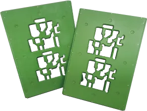 |
Protects surface mount components from the heat of the solder bath. |
|---|---|
| The carrier pallet protects previously mounted surface mount components from being damaged by heat as they pass through the flow solder bath. | |
| Prevents solder from adhering to surface mount components. | |
| The carrier pallet is open only where the leads of insertion-mounted components protrude so that they can be soldered. By setting the PCB on the carrier pallet, flux and solder do not adhere to previously mounted surface mount components. | |
| Periodic cleaning of the carrier pallet is important because solder can creep up due to flux adhering to the edge of the carrier pallet opening (edge), and solder can also adhere to the masked area. | |
▼▽Cleaning the flow pallet is explained on the following page!▽▼ | |
 |
Products information
|
|---|---|
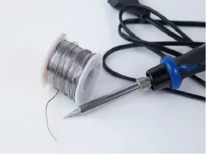
Although the soldering process is increasingly automated, manual soldering (also called hand soldering) using an electric soldering iron is used in the following cases.
 |
Modification and Repair of Components |
|---|---|
| When some components mounted on PCBs are not in good soldering condition, or when component failure or design changes occur, it is necessary to correct them by manual soldering. | |
| Resistance of components | |
| In some cases, reflow soldering or flow soldering is avoided due to the heat resistance of the component or the solvent resistance of the component. Manual soldering is performed while understanding the reason why the relevant component is to be retrofitted and giving individual consideration. |
| The manual soldering process is divided into cleaning, heating, solder supply, and flux cleaning. | |
| ①cleaning | Clean the soldering area with alcohol since oxidized soldering area and contaminants such as oil, grease, and sebum may interfere with the soldering process. |
| ②Heating | Heat the soldering iron. Pay attention to the temperature setting of the tip, the optimum joining temperature, and the melting temperature of the solder. |
| ③Solder supply | Solder is supplied to the right place at the right time by positioning and angling the soldering iron. |
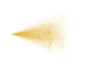
| ④Flux cleaning | Flux residue is cleaned from the soldered area. In many cases, localized cleaning is performed by rubbing with cotton swabs soaked in cleaning solvent or by using a spray-type cleaning agent. |
| Manual soldering operations may seem simple, but they are critical operations that directly affect the reliability of electronic components and products. Proper solder amount, solder wetting spread, etc. are established as mounting standards in JIS C 61191. Some companies offer soldering training and soldering certification. | |
Standard Micro Soldering Technology, 3rd Edition
Japan Welding Engineering Society, Micro Soldering Education Committee [ed.]
Nikkan Kogyo Shimbun
| Please be as specific as possible in your inquiry. Depending on the contents of your inquiry, it may take some time for us to reply to you. If you need product documentation (SDS/safety data sheets, TDS, instruction manuals, etc.), please contact us via “Request for SDS and other product documentation” ※Sales message through the inquiry form are strictly prohibited. |
KAKEN TECH, MICROCLEANER, MICROCLEAN&MARKLESS and MARKLESS are trademarks of KAKEN TECH CO., LTD. in PRC.
KAKEN TECH is a trademark of KAKEN TECH CO., LTD. in the U.S..